
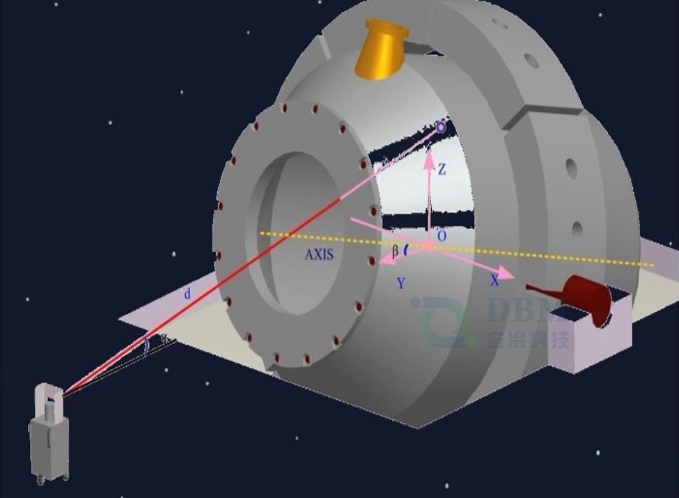
The product precisely measures the furnace lining thickness using a pulsed laser beam, enabling the reconstruction of a 3D point cloud of the converter’s outline. By emitting a pulsed laser beam onto the surface of the converter lining and receiving the returned laser, the product measures its flight time and corresponding changes, determining the distance and angle of the target point. This allows for the rapid formation of the converter lining area or surface outline information. Combined with the converter shell, coordinate transformation is used to obtain the furnace lining information.

Measuring the remaining thickness of the refractory bricks in the lining to prevent steel penetration accidents.
Estimating the molten pool level, furnace volume changes, and slag line position to optimize oxygen lance position and flow rate, guiding the steelmaking process.
Based on the distribution of weak areas in the lining, guiding slag splashing protection and the timing and location of repairs to avoid leaks or over-repairs.
Based on the lining thickness data, localized repairs can be performed on severely eroded areas, extending the converter’s service life, reducing the frequency of cold repairs, and thus saving on refractory material costs for lining repairs.
Establishing a converter lining change trend model during its service life provides data support for rationally scheduling lining maintenance and improving production efficiency.
Furnace lining measurement accuracy: ±5mm
Maximum target temperature: 1700 degrees Celsius
Number of measurement points per second: 120,000-1,000,000 (points/second)
Measurement distance range: 2-30m
Single scan time: less than 20s (excluding positioning)
Full furnace surface scan time: 4-6 minutes
Measurement laser type: Type I (eye-friendly)
The fixed furnace lining thickness measurement system using 3D laser scanning employs a brand-new imported high-speed 3D laser scanner, resulting in a significant leap in measurement speed. The 3D laser scanning furnace lining thickness measurement system (hereinafter referred to as the “furnace lining thickness measurement system”) works by emitting a directional pulsed laser beam from the 3D laser scanner onto the inner lining surface of the converter being measured, and receiving the returned laser beam to measure its flight time and waveform phase difference. This allows for the calculation of the distance and relative orientation between the instrument and the target point. Through coordinate transformation algorithms, the system ultimately obtains the 3D contour and thickness information of the measured area of

2-3 meters from the tapping side of the converter, at the furnace opening. The horizontal center of the laser scanning module should be approximately aligned with the center of the converter. The height should be chosen to ensure safety and avoid collisions while not interfering with the operation of other equipment on site.
Furnace lining measurement accuracy: ±5mm
Maximum target temperature: 1700 degrees Celsiu
Number of measurement points per second: 120,000-1,000,000 (points/second)
Measurement distance range: 2-30m
Single scan time: less than 20s (excluding positioning)
Full furnace surface scan time: 4-6 minutes
Measurement laser type: Type I (eye-friendly)
The DBM ladle/converter lining thickness measurement system has been successfully implemented in many steel mills, with an onsite video as below: